Index
Brief Introduction
- Communication is on TCP Port 179
- Uses Autonomous Systems (AS) to share routes. These can be internally in the AS (iBGP) or externally with other peers (eBGP).
- BGP is used internally (iBGP) within the AS, or externally (eBGP) between AS’s
- Slow but very customizable by nature since it has to support and share thousands of routes
What’s an Autonomous System?
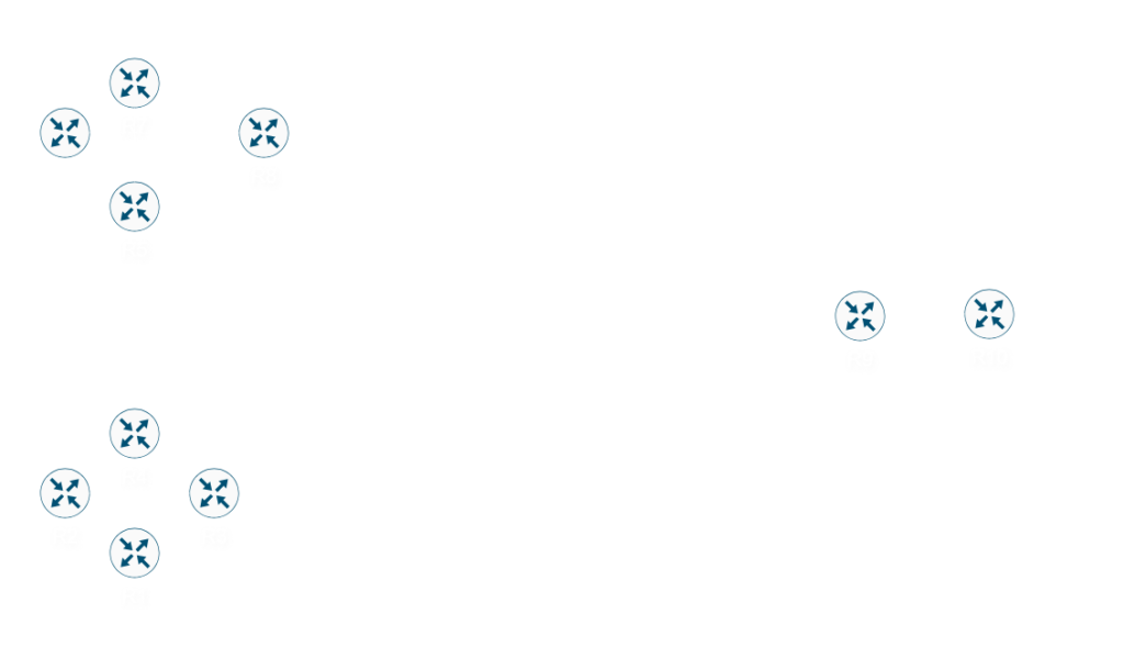
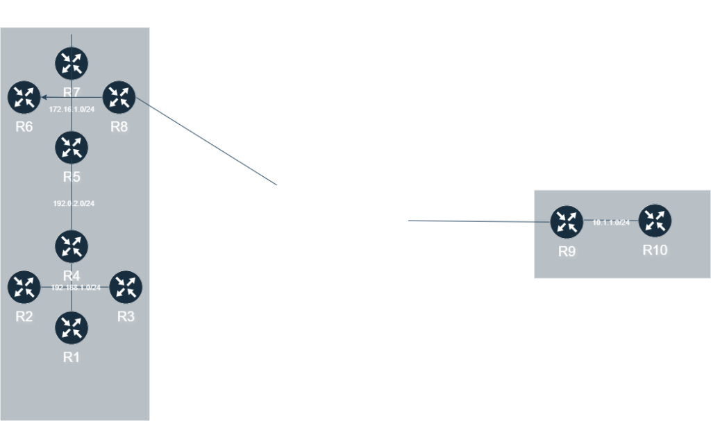
An autonomous system in simplicity defines a network that an administration controls. R1, R2, R3, and R4 in the example above is considered BGP AS 65500. Additionally, BGP AS 65000 consists of R5, R6, R7, and R8. Finally, BGP AS 65100 consists of R9 and R10.
Within an AS, is where Interior Gateway Protocols (IGP) live. Some of the most common IGP’s are OSPF, IS-IS, EIGRP, Static Routes, and even RIP (yay….). They are considered IGP because they control the routing internally in the AS.
AS Numbers as both private and public ranges just like IPv4 Addresses that range from 0 to 65535:
- 0: reserved.
- 1-64.495 – Public AS’s
- 64.496 – 64.511 – Used in documentation
- 64.512 – 65.534 – Private AS’s
- 65.535 – reserved
Newer devices support something called 4-byte AS. With this enabled, our AS ranges can be increased from 0 to 4294967295. Thus making 4200000000 to 4294967294 a new private range.
Peering
As mentioned earlier, there is two types of BGP Peers:
- iBGP – Peering between two routers in the same AS (Internal BGP)
- eBGP – Peering between two routers in different AS’s (External BGP)
In the example above, if the routers within AS 65500 (R1, R2, R3, and R4) peer with each other, this will be considered iBGP (Internal BGP). If R4 (AS 65500) and R5 (65000) peer with each other, this is considered eBGP (External BGP).
In order to peer, there has to various parameters that have to be agreed upon:
- The AS number their assigned to
- Neighbor Statements – Both neighbors have to the other’s IP address configured
- Matching BGP Versions
- Router-ID has to be unique
- Address Family Agreement (IPv4, IPv6, etc.)
- MD5 Authentication (If configured)
The router-id (RID) is a way of identifying the peer incase the peer is using multiple IP addresses with BGP. The RID will look just like an IPv4 Address, and is can be automatically set with an IPv4 address. The way the RID is gotten is based on the following typically, but is subject to change to change depending on vendor:
- Manually Set (Recommended)
- Highest IP address of any Loopback that is up
- If there is no loopbacks, highest IP of an interface that is up
The two timers we have to be aware of when establishing peering is a keepalive timer and the holddown timer. The keepalive timer is kicked off every 60 seconds by default, and will send a packet telling the peer they’re still alive. The holddown timer is set to 180 by default, meaning if it doesn’t get a keepalive within 180 seconds, the peer will go down.
The holddown timer doesn’t have to be the same on both BGP peers, but if they’re not, the lowest holddown timer is set.
There is multiple different attributes that are shared between AS’s, or within the AS, depending on if using iBGP or eBGP. We will discuss all these attributes later on.
eBGP
eBGP will establish a peering between two different AS’s. For example, in the below topology, R5 and R4 will have a BGP peering, and R8 and R9 will have a BGP peering.
By default, eBGP peers will have to be one hop away (unlike iBGP which can be multiple hops away). You can turn on BGP Multi-hop, which will allows the BGP peers to be more then one hop away.
iBGP
iBGP is special in terms of configuration. Unlike other routing protocols, all BGP enabled routers in the AS has to be peer with each other, even if multiple hops away. Additionally, iBGP routes will not be propagated between each peer either (Read below).
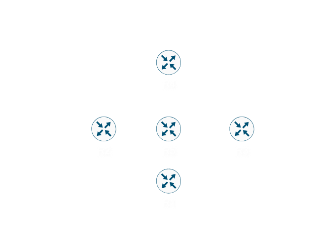
If we look at the above topology, if R2 sends the route 192.168.1.0/24 over to R3, then R3 won’t be able to advertise it to any of the BGP routers in the area. This is due to the fact everything, by default, should have a fully meshed peering in the AS. Meaning, R1 should peer with R2, R3, R4, and R5. R2 should peer with R1, R3, R4, and R5. This will continue until you are peering each router in the AS with another router.
To make this more scalable, we can implement route reflectors (discussed in another post at a later time), so you can only peer with only a couple of routes, and those routers are able to propagate routes to each other.
One of the main reasons we need to use iBGP is share attributes learned from routes between different AS’s, so no information is lost.
BGP Peering States
BGP will have neighbor states (see the description of the states below):
- Idle
- Connect
- Active
- OpenSent
- OpenConfirm
- Established
The states will go from Idle all the way to Established when attempting to peer with another router. However, when a peer is “active” it is considered a bad state to be in (More on this below).. At each one of these states, BGP will negotiate different values in order to establish a good session, then start sending routes in the established state. So we should expect all our peers to be in the established state at the very end.
Idle
This will be the initial state we start out in. If we’re stuck in this state, then we will usually have one of two problems:
- There is no route to the peer we identified
- If multi-hop isn’t enabled, the peer isn’t directly connected for eBGP peers
The 2nd problem is important because eBGP by default expects all their peers to be directly connected, since they will have a TTL (Time-to-Live) of 1 for eBGP. We can change this parameter with the multi-hop setting, which will tell the router how many hops the router is away, up to 255 hops away. This TTL will decrement by one along the path, so we want to pick a TTL count that can satisfy how many hops away.
For iBGP this default TTL is 255, so we should haven’t a problem TTL, unless there is a routing loop in the network.
Connect
The connect state means we we’re able to send a SYN packet to the peer, but we have yet to receive a SYN/ACK back. The important on this step is that we are dealing with the three-way handshake. Meaning, we need to complete the three-way handshake (SYN -> SYN/ACK -> ACK) with the peer on TCP port 179.
If we are successfully able to complete the three-way handshake, we will go into the OpenSent state.
If we have any problems in this state, we will usually have a retry timer of usually 30 seconds before we go into the Active state to indicate a problem.
Active
The active state is one of the problematic states of BGP. Peers stuck in the active state indicate there is an issue with the TCP connection. Active state will “actively” try to reach out to the peer, and eventually will end the connection to go back to the connect state again.
If we see a peer stuck in active, we should check one of the following:
- Route to the peer is incorrect/down
- IP of the peer is incorrect
- An Access-Control List (ACL) or firewall is preventing the connection to establish
OpenSent
The OpenSent state is the connection is when we discussing the parameters of the BGP connections. So needless to say, we have to agree on the following parameters and make sure they are correct on both sides:
- BGP Versions
- Source IP of the packet is the same as neighbor statement
- AS number must match neighbor statement
- The RID is unique
- Security Parameters (TTL/Password) is correct for what is expected
If none of these parameters is what is expected, will send an error code back to the peer describing where the mismatch is in the form of a “BGP Notification” packet. More information on this will be in the “BGP Messages” section.
OpenConfirm
The OpenConfirm state means we agree on the parameters in the OpenSent state, and we will begin sending keepalives to the peer. More information on keepalives will be found in the “BGP Messages” section.
Once we receive a keepalive in this state from the peer, we will finally go into the established state.
Established
Once we start receiving keepalives in from the peer, we will go into established, and start sending “BGP Update” packets and continue sending keepalives. These update packets will contain a section called NLRI (Network Layer Reachability Information), that will describe networks as well as the attributes that belong to those networks. More information on the update packets can be found in the BGP Messages section.
Once we get into the established state, everything is working as intended, and make sure we allow/redistribute the routes we want to send/receive.
From here if there is any issues with the BGP session, we will declare the peer as down. Some of the common problems that will happen with this is the following:
- Network migration, software, or hardware upgrades
- Keepalives not being received due to drops in-between or transmission/receiving errors
- High CPU could be dropping any packets, including the keepalives
- The process controlling BGP crashed
- Configuration changes in BGP needing to restart the connection
BGP Message Types
In order to exchange information pertaining to BGP, there is four different message types that will be sent:
- Keepalive
- Open
- Notification
- Update
All four of these messages will be used in both iBGP and eBGP and will ultimately decide what BGP should do.
Keepalive
The keepalive message will usually be sent 60 seconds by default. This will ensure BGP will stay alive as long as we are sending and receiving these. By default, if we don’t receive a keepalive within 180 seconds (the holddown timer), the BGP session will drop and we will have to reestablish everything again.
Open
The open message is sent right after the three-way handshake is established. This essentially tells the peer, “Hey, since we have bidirectional communication, let’s go ahead and OPEN for BGP communication.” These will send some of the following parameters:
- BGP Version
- Hold Time
- AS Number
- Router-ID
- Optional Parameters
The optional parameters contain can be Graceful Restart, Route-Refresh, and some other ones that are optional. These will be discussed in another article, but since these are optional, it will just tell the peer, “I support the following parameters” so it know what enhancements to offer.
Notification
When an error is detected during the establishment of the peering, or even after the establishment of the peer, we will send an error message indicating there is an issue with the connection. These error message can range from “Bad Peer AS” to “Cease – Connection Rejected”.
You don’t have to memorize these, but vendors will usually have a command to view what error codes were sent/received.
| Error Code | Subcode | Description |
|---|---|---|
| 01 | 00 | Message Header Error |
| 01 | 01 | Message Header Error – Connection not Synchronized |
| 01 | 02 | Message Header Error – Bad Message Length |
| 01 | 03 | Message Header Error – Bad Message Type |
| 02 | 00 | Open Message Error |
| 02 | 01 | Open Message Error – Unsupported Version Number |
| 02 | 02 | Open Message Error – Bad Peer AS |
| 02 | 03 | Open Message Error – Bad RID |
| 02 | 04 | Open Message Error – Unsupported Optional Parameter |
| 02 | 05 | Open Message Error – Deprecated |
| 02 | 06 | Open Message Error – Unacceptable Hold Time |
| 02 | 07 | Open Message Error – No Supported Capability Value (Cisco) |
| 02 | 08 | Open Message Error – No Supported AFI/SAFI (Cisco) |
| 02 | 09 | Open Message Error – Grouping Conflict (Cisco) |
| 02 | 0A | Open Message Error – Grouping Required (Cisco) |
| 03 | 00 | Update Message Error |
| 03 | 01 | Update Message Error – Malformed Attribute List |
| 03 | 02 | Update Message Error – Unrecognized Well-Known Attribute |
| 03 | 03 | Update Message Error – Missing Well-Known Attribute |
| 03 | 04 | Update Message Error – Attribute Flags Error |
| 03 | 05 | Update Message Error – Attribute Length Error |
| 03 | 06 | Update Message Error – Invalid Origin Attribute |
| 03 | 07 | (Deprecated) |
| 04 | 00 | Hold Timer Expired |
| 05 | 00 | Finite State Machine Error |
| 06 | 00 | Cease |
| 06 | 01 | Cease – Maximum Number of Prefixes Reached |
| 06 | 02 | Cease – Administrative Shutdown |
| 06 | 03 | Cease – Peer Deconfigured |
| 06 | 04 | Cease – Administrative Reset |
| 06 | 05 | Cease – Connection Rejected |
| 06 | 06 | Cease – Other Configuration Change |
| 06 | 07 | Cease – Connection Collision Resolution |
| 06 | 08 | Cease – Out of Resources |
Configuration – Cisco
In order to configure BGP peering, we must keep in mind several things:
- iBGP must have have a route to the peer, even if it’s on a subnet. Relies on IGP (Static Route, OSPF, IS-IS, etc.) to get connectivity
- Must have TCP Port 179 Connnectivity
- Need multi-hop or ttl-security if using eBGP on a peer that’s more then one hop away.
First thing to do is to ensure that we have the correct route to the peer. On R1, we should have a route to all our peers for at least iBGP. This means we should have a route to R2 all the way to R8. When we look at show ip route (below), we can see there is a static route to all the peers:
R1#show ip route
Codes: L - local, C - connected, S - static, R - RIP, M - mobile, B - BGP
       D - EIGRP, EX - EIGRP external, O - OSPF, IA - OSPF inter area
       N1 - OSPF NSSA external type 1, N2 - OSPF NSSA external type 2
       E1 - OSPF external type 1, E2 - OSPF external type 2
       i - IS-IS, su - IS-IS summary, L1 - IS-IS level-1, L2 - IS-IS level-2
       ia - IS-IS inter area, * - candidate default, U - per-user static route
       o - ODR, P - periodic downloaded static route, H - NHRP, l - LISP
       a - application route
       + - replicated route, % - next hop override, p - overrides from PfR

Gateway of last resort is not set

      1.0.0.0/32 is subnetted, 1 subnets
C        1.1.1.1 is directly connected, Loopback0
      10.0.0.0/24 is subnetted, 1 subnets
S        10.1.1.0 [1/0] via 192.168.1.4
      172.16.0.0/24 is subnetted, 1 subnets
S        172.16.1.0 [1/0] via 192.168.1.4
S     192.0.2.0/24 [1/0] via 192.168.1.4
      192.168.1.0/24 is variably subnetted, 2 subnets, 2 masks
C        192.168.1.0/24 is directly connected, GigabitEthernet0/0
L        192.168.1.1/32 is directly connected, GigabitEthernet0/0
S     203.0.113.0/24 [1/0] via 192.168.1.4
Next thing we need to ensure is that we have a loopback with our RID to ensure there a small chance of it going down. Looking at the config below, in addition to the physical interface, we can see there is a loopback with the IP of 1.1.1.1 that will also be the RID:
R1#sh run | sec interface
interface Loopback0
 ip address 1.1.1.1 255.255.255.255
interface GigabitEthernet0/0
 ip address 192.168.1.1 255.255.255.0
 duplex auto
 speed auto
 media-type rj45
Lastly, we will need to define our BGP peers and the router id. We can do this with the following commands:
R1#sh run | sec router
router bgp 65000                       !65000 is the current AS the router is in
 bgp router-id 1.1.1.1                 !We will manually define the RID that is assigned to the loopback (best practice)
 bgp log-neighbor-changes              !Will let us know when BGP peers drop
 neighbor 172.16.1.5 remote-as 65000   !Here we are defining our peer as R5, and in the AS of 65000, making this an iBGP peer since AS is same
 neighbor 172.16.1.6 remote-as 65000   !Peer is R6 and iBGP peer
 neighbor 172.16.1.7 remote-as 65000   !Peer is R7 and iBGP peer
 neighbor 172.16.1.8 remote-as 65000   !Peer is R8 and iBGP peer
 neighbor 192.168.1.2 remote-as 65000  !Peer is R2 and iBGP peer
 neighbor 192.168.1.3 remote-as 65000  !Peer is R3 and iBGP peer
 neighbor 192.168.1.4 remote-as 65000  !Peer is R4 and iBGP peer
We will pretty much use this same config on all routers throughout the area. For example, here will be a output of R7:
R7#sh run | sec router
router bgp 65000
 bgp router-id 7.7.7.7
 bgp log-neighbor-changes
 neighbor 172.16.1.5 remote-as 65000
 neighbor 172.16.1.6 remote-as 65000
 neighbor 172.16.1.8 remote-as 65000
 neighbor 192.168.1.1 remote-as 65000
 neighbor 192.168.1.2 remote-as 65000
 neighbor 192.168.1.3 remote-as 65000
 neighbor 192.168.1.4 remote-as 65000
The one configuration we will have to take note of is where R4 comes into play. Imagine if we have a VPN or something along those lines between R4 and R5, the problem here will be when the BGP packets leave R4, it will leave with the of the external interface (192.0.2.4). Meaning, that Source IP of the packets is 192.0.2.4. However since we are working with iBGP, we will want to use our Private IP (192.168.1.4). To do this, we will have to use a command to tell BGP where to source the packets from:
R4#sh run | sec router
router bgp 65000
 bgp router-id 4.4.4.4
 bgp log-neighbor-changes
 neighbor 172.16.1.5 remote-as 65000
 neighbor 172.16.1.5 update-source GigabitEthernet0/0 !BY using the update-source subcommand, we ensure that our source IP will be this interface, which is 192.168.1.4
 neighbor 172.16.1.6 remote-as 65000
 neighbor 172.16.1.6 update-source GigabitEthernet0/0
 neighbor 172.16.1.7 remote-as 65000
 neighbor 172.16.1.7 update-source GigabitEthernet0/0
 neighbor 172.16.1.8 remote-as 65000
 neighbor 172.16.1.8 update-source GigabitEthernet0/0
 neighbor 192.168.1.1 remote-as 65000
 neighbor 192.168.1.2 remote-as 65000
 neighbor 192.168.1.3 remote-as 65000
The two routers that will be somewhat different is R8 and R9, since we will be establishing an eBGP neighbors. All peers up to this point have been iBGP:
R8#sh run | sec router
router bgp 65000                     !Our current AS
 bgp router-id 8.8.8.8
 bgp log-neighbor-changes
 redistribute static                 !Redistributes static-routes (see verification section to verify)
 neighbor 172.16.1.5 remote-as 65000
 neighbor 172.16.1.6 remote-as 65000
 neighbor 172.16.1.7 remote-as 65000
 neighbor 192.168.1.1 remote-as 65000
 neighbor 192.168.1.2 remote-as 65000
 neighbor 192.168.1.3 remote-as 65000
 neighbor 192.168.1.4 remote-as 65000
 neighbor 203.0.113.9 remote-as 65100 !Main difference is this command here. You can see we are peering with R9, but the remote-AS (65100) is different then our current AS (65000), indicating this will be a eBGP peer.
 default-information originate      !Indicates the default route will be redistributed to the peers
We will discuss more about redistribution of routes in another blog post. By doing redistribution wrong, we can easily cause routing loops.
R9#sh run | sec router
router bgp 65100                      !Our current AS is 65100
 bgp router-id 9.9.9.9
 bgp log-neighbor-changes
 neighbor 10.1.1.10 remote-as 65100   !This will be the iBGP peer (R10) since the remote-as and our AS is the same
 neighbor 203.0.113.8 remote-as 65000 !This will be the eBGP peer, since our peer is in the remote-as 65000 and our current AS is 65100
After we configure, we can check to verify if everything is working correctly with the following section.
Verification
We have various commands to ensure we have connectivity and do basic troubleshooting. First, we can check the state with show ip bgp summary:
R8#show ip bgp summ
BGP router identifier 8.8.8.8, local AS number 65000                     //Here we can see our RID, and our ASN
BGP table version is 1, main routing table version 1

Neighbor        V           AS MsgRcvd MsgSent   TblVer  InQ OutQ Up/Down  State/PfxRcd  //These will show us neighbors, their AS, and uptime
172.16.1.5      4        65000    3205    3213        1    0    0 2d00h           0
172.16.1.6      4        65000    3206    3211        1    0    0 2d00h           0
172.16.1.7      4        65000    3211    3214        1    0    0 2d00h           0
192.168.1.1     4        65000    3209    3202        1    0    0 2d00h           0
192.168.1.2     4        65000    3206    3205        1    0    0 2d00h           0
192.168.1.3     4        65000    3208    3206        1    0    0 2d00h           0
192.168.1.4     4        65000    3207    3211        1    0    0 2d00h           0
203.0.113.9     4        65100      23      23        1    0    0 00:17:35        0    //We can see the uptime here is only 17 minutes
In the above command, if we had any issues with our neighbors, we will the stat information listed above. For example, if we down the interface on R4 with the IP of 192.0.2.4, you will notice, that the neighbors on R1 will go into Active state, due to lack of TCP connectivity:
R1#sh ip bgp summ
BGP router identifier 1.1.1.1, local AS number 65000
BGP table version is 9, main routing table version 9

Neighbor        V           AS MsgRcvd MsgSent   TblVer  InQ OutQ Up/Down  State/PfxRcd
172.16.1.5      4        65000       0       0        1    0    0 00:01:18 Active
172.16.1.6      4        65000       0       0        1    0    0 00:00:51 Idle
172.16.1.7      4        65000       0       0        1    0    0 00:01:29 Idle
172.16.1.8      4        65000       0       0        1    0    0 00:01:31 Idle
192.168.1.2     4        65000    3321    3322        9    0    0 2d02h           0
192.168.1.3     4        65000    3312    3316        9    0    0 2d02h           0
192.168.1.4     4        65000    3310    3311        9    0    0 2d02h           0
R1#sh ip bgp summ
BGP router identifier 1.1.1.1, local AS number 65000
BGP table version is 9, main routing table version 9

Neighbor        V           AS MsgRcvd MsgSent   TblVer  InQ OutQ Up/Down  State/PfxRcd
172.16.1.5      4        65000       0       0        1    0    0 00:01:20 Active
172.16.1.6      4        65000       0       0        1    0    0 00:00:54 Idle
172.16.1.7      4        65000       0       0        1    0    0 00:01:32 Active
172.16.1.8      4        65000       0       0        1    0    0 00:01:34 Idle
192.168.1.2     4        65000    3321    3322        9    0    0 2d02h           0
192.168.1.3     4        65000    3312    3316        9    0    0 2d02h           0
192.168.1.4     4        65000    3310    3311        9    0    0 2d02h           0
From the above output, you can see the peers 172.16.1.5, 172.16.1.6, 172.16.1.7, and 172.16.1.8 is flapping because the state is going between Active/Idle. if we got back to our notes above, we can see the active state means the following:
The active state is one of the problematic states of BGP. Peers stuck in the active state indicate there is an issue with the TCP connection. Active state will “actively” try to reach out to the peer, and eventually will end the connection to go back to the connect state again.
If we see a peer stuck in active, we should check one of the following:
- Route to the peer is incorrect/down
- IP of the peer is incorrect
- An Access-Control List (ACL) or firewall is preventing the connection to establish
A way we can verify we don’t have TCP Port 179 connectivity is by using telnet. By using telnet <IP> 179 we can check to see if we have connectivity to the peer:
R1#telnet 172.16.1.5 179
Trying 172.16.1.5, 179 ...
% Destination unreachable; gateway or host down               #By looking here, we can't reach the host because it's down

R1#telnet 192.168.1.4 179
Trying 192.168.1.4, 179 ... Open                              #By getting "open" here, that means we can connect on port 179
We can use show ip bgp neighbor <IP> routes, we can see the routes received by that peer:
R6#show ip bgp neighbor 172.16.1.8 routes
BGP table version is 5, local router ID is 6.6.6.6
Status codes: s suppressed, d damped, h history, * valid, > best, i - internal,
              r RIB-failure, S Stale, m multipath, b backup-path, f RT-Filter,
              x best-external, a additional-path, c RIB-compressed,
Origin codes: i - IGP, e - EGP, ? - incomplete
RPKI validation codes: V valid, I invalid, N Not found

     Network          Next Hop            Metric LocPrf Weight Path
 *>i 0.0.0.0          203.0.113.9              0    100      0 ?
 *>i 10.1.1.0/24      203.0.113.9              0    100      0 ?
 r>i 192.0.2.0        172.16.1.5               0    100      0 ?
 r>i 192.168.1.0      172.16.1.5               0    100      0 ?

Total number of prefixes 4
We can see above, we are learning three routes from R8 (172.16.1.8), being 0.0.0.0, 10.1.1.0/24, 192.0.2.0/24, and finally 192.168.1.0/24. To verify that R8 is sending these, can run sh ip bgp neighbor <IP> advertised-routes to show all the routes we have been advertising.
R8#sh ip bgp neighbor 172.16.1.6 advertised-routes
BGP table version is 5, local router ID is 8.8.8.8
Status codes: s suppressed, d damped, h history, * valid, > best, i - internal,
              r RIB-failure, S Stale, m multipath, b backup-path, f RT-Filter,
              x best-external, a additional-path, c RIB-compressed,
Origin codes: i - IGP, e - EGP, ? - incomplete
RPKI validation codes: V valid, I invalid, N Not found

     Network          Next Hop            Metric LocPrf Weight Path
 *>  0.0.0.0          203.0.113.9              0         32768 ?
 *>  10.1.1.0/24      203.0.113.9              0         32768 ?
 *>  192.0.2.0        172.16.1.5               0         32768 ?
 *>  192.168.1.0      172.16.1.5               0         32768 ?

Total number of prefixes 4