Index
Fundamentals
Please read the IGMP section before continuing if you need a brief overview of IGMP:
IGMP Made Easy: Your Introduction to Internet Group Management Protocol
During the routing of multicast packets via PIM, or Protocol Independent Multicast, we not only have to keep track of the destination, but also of the sources where the traffic is coming from. In order for PIM to work as intended, we will have to take advantage of the underlying unicast routing protocol (BGP, OSPF, IS-IS, EIGRP, Static, etc.) to make sure everything get where it’s needed.
Group States
We have to keep track of specific group multicast traffic. We refer to these as (*,G) and (S,G), pronounced Star G and S G accordingly. Each one of the group states provide forwarding an flow information in the form of a “state table. ON a cisco router, you can view these with the command show ip mroute.
R1#sh ip mroute
IP Multicast Routing Table
Flags: D - Dense, S - Sparse, B - Bidir Group, s - SSM Group, C - Connected,
       L - Local, P - Pruned, R - RP-bit set, F - Register flag,
       T - SPT-bit set, J - Join SPT, M - MSDP created entry, E - Extranet,
       X - Proxy Join Timer Running, A - Candidate for MSDP Advertisement,
       U - URD, I - Received Source Specific Host Report,
       Z - Multicast Tunnel, z - MDT-data group sender,
       Y - Joined MDT-data group, y - Sending to MDT-data group,
       G - Received BGP C-Mroute, g - Sent BGP C-Mroute,
       N - Received BGP Shared-Tree Prune, n - BGP C-Mroute suppressed,
       Q - Received BGP S-A Route, q - Sent BGP S-A Route,
       V - RD & Vector, v - Vector, p - PIM Joins on route,
       x - VxLAN group
Outgoing interface flags: H - Hardware switched, A - Assert winner, p - PIM Join
 Timers: Uptime/Expires
 Interface state: Interface, Next-Hop or VCD, State/Mode

(*, 239.0.1.2), 00:14:37/stopped, RP 4.4.4.4, flags: SPF
  Incoming interface: GigabitEthernet0/1, RPF nbr 10.1.1.2
  Outgoing interface list: Null

(192.168.1.10, 239.0.1.2), 00:14:37/00:02:54, flags: FT
  Incoming interface: GigabitEthernet0/0, RPF nbr 0.0.0.0
  Outgoing interface list:
    GigabitEthernet0/1, Forward/Sparse, 00:14:37/00:02:41

(*, 239.255.255.250), 00:34:00/00:02:18, RP 4.4.4.4, flags: SJC
  Incoming interface: GigabitEthernet0/1, RPF nbr 10.1.1.2
  Outgoing interface list:
    GigabitEthernet0/0, Forward/Sparse, 00:33:58/00:02:18

(*, 224.0.1.40), 09:40:27/00:02:39, RP 4.4.4.4, flags: SJCL
  Incoming interface: GigabitEthernet0/1, RPF nbr 10.1.1.2
  Outgoing interface list:
    Loopback0, Forward/Sparse, 09:40:26/00:02:39
In the above output you can see we have one (S,G) entry which is (192.168.1.10, 239.0.1.2) and then we have the three (*,G) entries: (*, 239.0.1.2), (*, 239.255.255.250), and (*, 224.0.1.40).
The (192.168.1.10, 239.0.1.2) is an (S,G) entry that indicates that this connection is a multicast stream that we know the source for, so we have to find the shortest path back, or the shortest path tree.
The (*,G) indicates a multicast stream that we’re interested in and we have need for. It indicates that this stream can signal upstream routers for membership. You will see this router on the branches to show where the leaves are supposed to be.
In other words, we will need a (*,G) entry to have a (S,G) entry. The (*,G) just says we’re interested in a stream, while the (S,G) indicates that we have a source that needs the stream.
How these entries get build and know which interface to pick for traffic depends on which PIM Mode you are using (Sparse/Dense/SSM). We will be discussing this later on.
Trees
In order to understand how a multicast packet gets to where it’s needed, we will have to understand the concept the trees. By using trees, we can save resources on a gateway/router to only include information that’s needed to pass that traffic, and not the entire network. It will use the underlying routing protocol to do process known as building the tree.
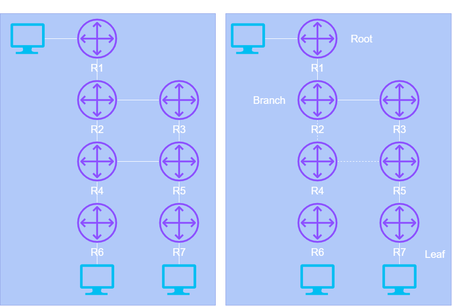
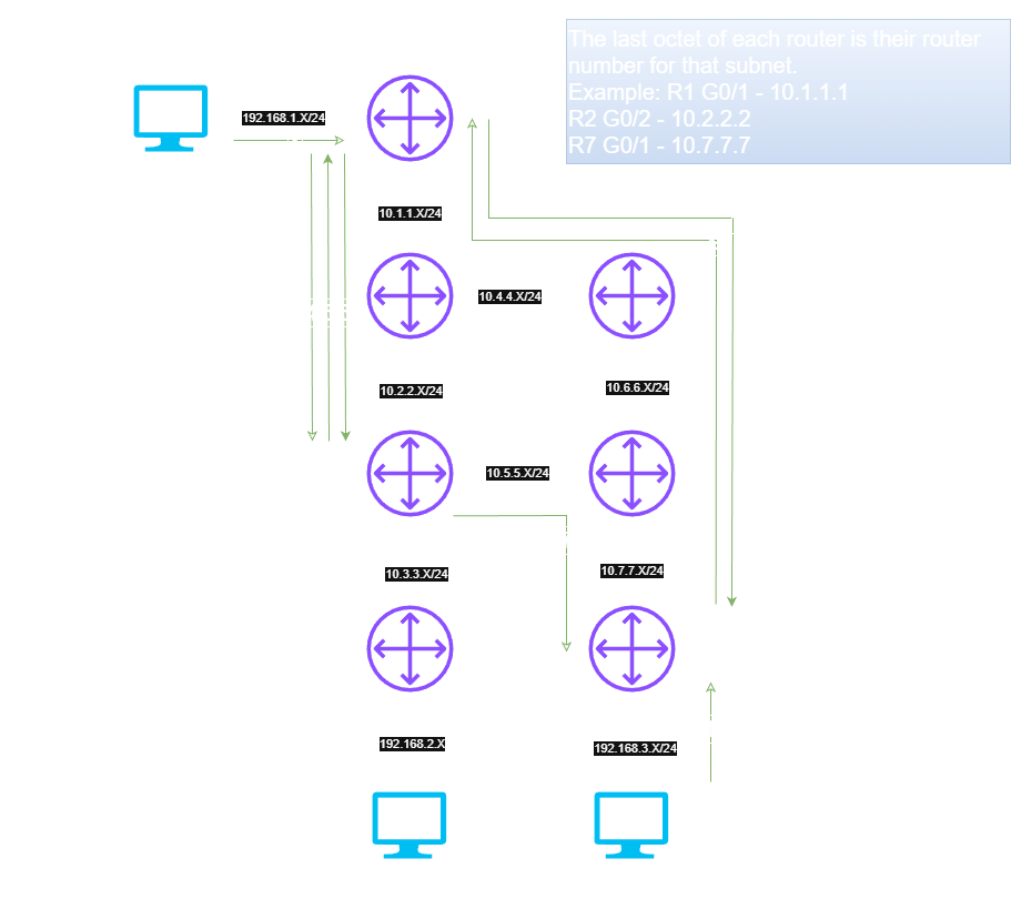
This network tree will be the correct path to avoid any loop avoidance, best efficiency, and predictive failovers. Each device will pick the best path for the multicast traffic to be sent, and will ultimately come together to make a tree like in the “Multicast Stream” topology above.
The root of the tree is the router closest to the source of that multicast stream. So in the above, The root will be R1. The leaf will be any router that is the closest to the receiver, which in this case is R7. Lastly, the branch is any router that has to replicate the traffic in order to reach the leaves. So in this this, R2, R3 and R5 would be considered the branch routers.
There will be two types of trees that PIM will be building:
- Source Trees (Shortest Path Trees)
- Shared Trees
Source Trees
The Source Tree, or Shortest Path Trees, and builds a tree for each (S,G) entry in the network. This tree will be based on the unicast routing table, and will show the path the multicast traffic will take.
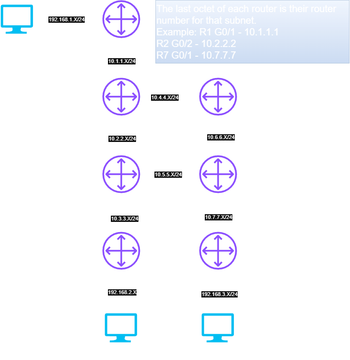
Let’s build a source tree on the following topology:

In the topology above, Host1 will be sending a multicast stream to 239.0.1.2, and our job is to follow it towards the receivers (Host2 and Host3). These shortest path trees are calculated based on reverse path forwarding (RPF), which will use the source IP to find the best path.
So first, let’s look at R6, who is connected Host2. We know the traffic should be coming from Host1, so we can use that as a baseline. If we look at our MFIB (Multicast Forwarding Information Base) with show ip mroute, we can see the (S,G) and (*,G) for the traffic from Host1:
(*, 239.0.1.2), 01:25:53/stopped, RP 4.4.4.4, flags: SJC
  Incoming interface: GigabitEthernet0/1, RPF nbr 10.3.3.4
  Outgoing interface list:
    GigabitEthernet0/0, Forward/Sparse, 01:25:53/00:02:08

(192.168.1.10, 239.0.1.2), 01:07:47/00:01:10, flags: JT
  Incoming interface: GigabitEthernet0/1, RPF nbr 10.3.3.4
  Outgoing interface list:
    GigabitEthernet0/0, Forward/Sparse, 01:07:47/00:02:08
So we can see we are interested in the 239.0.1.2 stream by looking at the (*,G) entry (*, 239.0.1.2). The reasons why we’re interested in this, is because sent us a IGMP Join messages indicating that it should receive all packets to 239.0.1.2, and to forward them out GigabitEthernet0/0. This interface will then get added to the OIL (Outgoing Interface List).
Next, we can also see a host sending packets to 239.0.1.2 from 192.168.1.10 with the (S,G) entry (192.168.1.10, 239.0.1.2). This is where the magic happens. We will use the source IP (192.168.1.10) to determine the best path back by using reverse path forwarding (RPF). We can do this with the command show ip route 192.168.1.10. This is why we need an underlying unicast working for multicast to work as intended. In this case, we are using OSPF make sure everyone knows of everyone:
R6#sh ip route 192.168.1.10
Routing entry for 192.168.1.0/24
  Known via "ospf 1", distance 110, metric 4, type intra area
  Last update from 10.3.3.4 on GigabitEthernet0/1, 01:31:34 ago
  Routing Descriptor Blocks:
  * 10.3.3.4, from 1.1.1.1, 01:31:34 ago, via GigabitEthernet0/1
      Route metric is 4, traffic share count is 1
By looking at the RPF, we can see 192.168.1.10 is coming from G0/1, which will become the IIL (Incoming Interface List), which belongs to R4, so we know we need to tell R4 we are interested in 239.0.1.2 by sending a PIM Join (More on this later):

Next, R4 will do the same thing, it will look at the MFIB to see all it’s entries, and do a RPF check:
(*, 239.0.1.2), 01:37:31/00:02:57, RP 4.4.4.4, flags: S
  Incoming interface: Null, RPF nbr 0.0.0.0
  Outgoing interface list:
    GigabitEthernet0/0, Forward/Sparse, 01:16:44/00:02:34
    GigabitEthernet0/1, Forward/Sparse, 01:37:31/00:02:57

(192.168.1.10, 239.0.1.2), 01:19:42/00:01:49, flags: T
  Incoming interface: GigabitEthernet0/2, RPF nbr 10.2.2.2
  Outgoing interface list:
    GigabitEthernet0/1, Forward/Sparse, 01:19:42/00:03:27
R4#sh ip route 192.168.1.10
Routing entry for 192.168.1.0/24
Known via "ospf 1", distance 110, metric 3, type intra area
Last update from 10.2.2.2 on GigabitEthernet0/2, 01:38:16 ago
Routing Descriptor Blocks:
* 10.2.2.2, from 1.1.1.1, 01:38:16 ago, via GigabitEthernet0/2
Route metric is 3, traffic share count is 1So now R4 will notify R2 that it needs the 239.0.1.2 stream, and this will continue on until it gets to R1, the leaf of the tree. Once it gets there, we got our shortest path tree.
Now, how the (S,G) entry gets to the router in the first place changes depending on PIM mode being used. This can be PIM Sparse/Dense/SSM. More on these later.
Shared trees, are a little different from Source Trees, since they all use a shared point on the network. This shared point becomes the root of the tree, and is called the Rendezvous Point (RP). The RP will know all the (*,G) in the entire PIM domain, and can build a tree RP first, then will use RPF check to build the Source Tree for the shortest path. Meaning, the RP can either be in the direct shortest path, or it can be outside of it.
This tree is used in Sparse Mode so everyone in the network doesn’t need to know about every single stream going on.
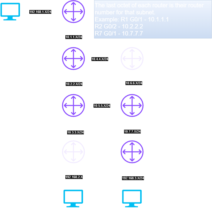
So in the above picture which shows the Shared Tree, it will go through the RP first. This will ensure the RP knows about the stream originally, and can make sure it gets to the receivers needed. Then when it gets to the receiver, there is a RPF check, to make sure it’s using the shortest path, which may or may not be through the RP.

So when the routers do the RPF check, the source tree, or the shortest path tree, will be through R3, so R4 wouldn’t be in the shortest path. You can see the change above.
Neighbors
The first thing we need to do in order to start sharing information between all the multicast routers is the neighborship between everyone. The way we start this process is by sending out hello messages. These Hello messages are sent out each PIM enabled interface with 224.0.0.13.
The hello messages are sent every 30 seconds to refresh any adjacencies. If there is no hello within the hold-time, the neighbor adjacency will go down. By default, it 3.5x the hello, so it is 105 seconds if not changed.
You can view these PIM neighborships with show ip pim neighbor:
R4#show ip pim neighbor
PIM Neighbor Table
Mode: B - Bidir Capable, DR - Designated Router, N - Default DR Priority,
      P - Proxy Capable, S - State Refresh Capable, G - GenID Capable,
      L - DR Load-balancing Capable
Neighbor          Interface                Uptime/Expires    Ver   DR
Address                                                            Prio/Mode
10.5.5.5          GigabitEthernet0/0       03:59:59/00:01:25 v2    1 / DR S P G
10.3.3.6          GigabitEthernet0/1       03:59:49/00:01:34 v2    1 / DR S P G
10.2.2.2          GigabitEthernet0/2       04:00:27/00:01:25 v2    1 / S P G
Designated Routers
PIM uses the concept of Designated Routers (DR) in order to control information and PIM updates for routers on the segment/subnet. There can only be DR per segment, so in order to elect that one DR, the highest priority number is picked, if that is the same, then the highest IP address is picked. There is a default DR priority of 1 on all PIM enabled interfaces.
When the DR receives an IGMP membership report for a host that wants to stream, it will send a PIM Join messages towards the RP, or source if using SSM. When the host leaves the group, it will send a PIM prune in order to remove the path from the distribution tree.
To maintain the PIM state, the closest router sends IGMP join-prune messages once per minute in order maintain state creation of both (*,G) and (S,G) with the following:
- State Creation of (*,G) Tree: The DR will send PIM join message towards the DR if it receives an IGMP (*,G) report
- State Creation of (S,G) Tree at Source: DR will send a register message towards the RP to let them know they have a host sending traffic. This will be the DR closest to the source.
- State Creation of (S,G) at Receivers: When a IGMP enabled receiver receives a (S,G) report, the DR will send a PIM Join towards the source
Different Modes
In order for multicast traffic to go from Sender to Receiver, there is three different methods in doing so:
- Dense
- Sparse
- SSM
Dense
Dense mode is probably one of the easiest configurations to implement, however, the main problem is that streams will be flooded across the entire network, and will only be pruned once ever three minutes.
The way dense mode works is that when a downstream router receives the multicast packet, it will go ahead and flood all other PIM routers and then those will notify others. If a router doesn’t need a stream, it will eventually respond with a prune, but may take upwards of three minutes for this prune. Meaning that this solution isn’t very scalable, and it’s really intended for small network with high speed connections.
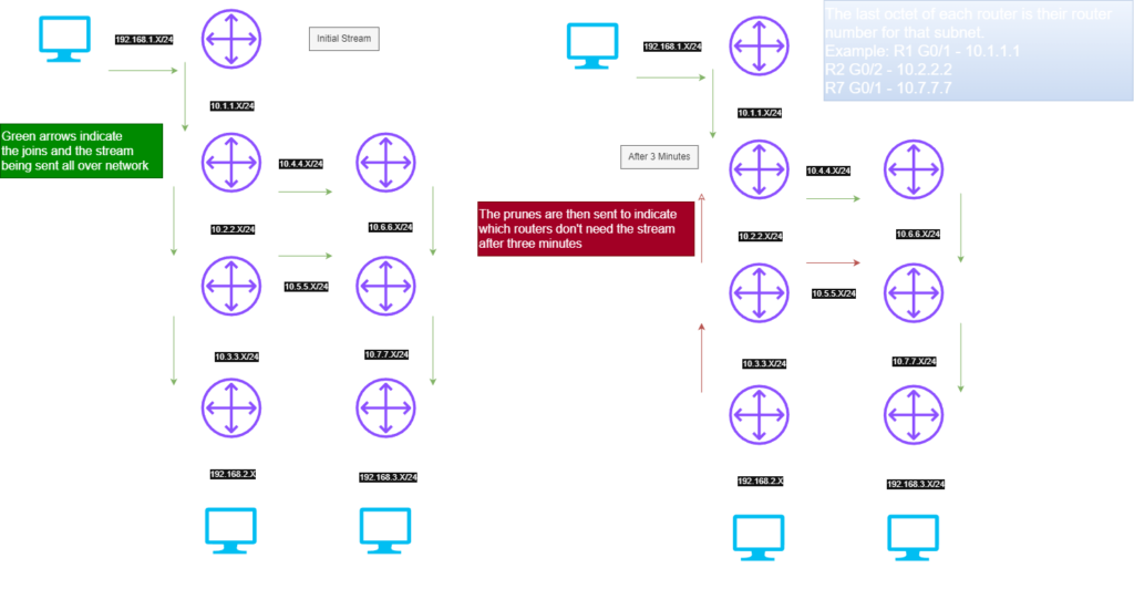
You can see from the picture above, when the initial stream is being sent out, it will send that multicast packet throughout the entire network. Even though Host2 isn’t receiving the traffic, that traffic will still be sent to R6.
After about 3 minutes, the routers will send prunes to their neighbors to indicate they have no interested receives, so this way we can now pick only a certain path.
Sparse
Instead of just spamming the packets the joins out all directions and eventually pruning the traffic, sparse mode takes a different approach. It will only forward the joins to those who need it by incorporating a rendezvous point (RP). The RP will know about all the sources and receivers in the Sparse Mode network.
The DR will send join/prune messages towards the RP, which can be group-specific. That way the RP will get information about receivers and sources, and will control where every packet will go initially.
With this in mind, every single router in the network should agree to same the RP that specific multicast group. That means, you can have the RP of 1.1.1.1 control the group 239.10.10.0/24, while RP of 2.2.2.2 control the group of 239.20.20.0/24.
Since the RP is the backbone of the multicast sparse network, everything needs to agree on the same one. There is one of three ways this can be done:
- Static
- Bootstrap Router (BSR)
- Auto-RP (Cisco Only)
- Anycast RP
Rendezvous Points
A static RP is defined manually on every single device throughout the multicast domain. This can be a tedious task, but is ensures that every device is the same.
Bootstrap Router (BSR)
This is an open standard protocol that provides an active/standby functionality while and doing all of this automatically. There is two roles used by BSR in order to determine the RP:
- Candidate BSR – This collects all information from all the RP’s in the network and will advertise it
- Candidate RP – The routers who want to become the RP in the network
The BSR will be elected based on the priority and IP address of any of the candidates. The highest priority will be elected first, but if all candidate BSR’s have the same priority, the highest BSR IP Address is elected next. The BSR messages are sent via 224.0.0.13 and only have a TTL of 1, meaning these messages won’t be routed across the network, instead, when the neighbor receives the BSR message, it will relay the BSR message through PIM enabled interfaces.
Each router on the network will send the a candidate RP advertisements to the BSR which will contain the multicast group they want to be responsible for, and their IP address. This information will be stored in the local candidate-RP cache, and the BSR will advertise the contents to all other PIM devices in the domain.
The Flow of Sparse Mode
Now since every single router has to agree on the RP, there has to be a very specific flow of events in order to make sure only the necessary routers get the multicast stream:
- The receiver will send an IGMP request to the Last Hop Router (LHR). The LHR is the router that that is closest to the receiver. The LHR will look at the RP for that multicast group, then sends a request to the RP. This will be shown as a (*,G) in the MFIB and will be a shared tree.
- The (*,G) should now be present at the RP. This way, the RP knows about all the receivers in that network.
- When the sender starts sending the multicast stream, the FHR should receive this multicast stream. The first hop router, or FHR, is the router closest to the source.
- When the FHR gets this multicast stream, it will send a unicast packet to the RP. The unicast packet is called a PIM register packet, and will contain information about the source and stream to the RP.
- Since the RP already has a interested receiver (the (*,G) entry from the LHR), it will send a (S,G) PIM Join towards the FHR, at the same time, it will send a PIM Register stop as another unicast to the FHR.
- When the FHR receives the register stop, it will send the multicast to the RP as an (S,G) flow, since we have the specific source.
- At this time, the RP will populate the outgoing list to the LHR based on the interested receivers from the (*,G) received in step 1 and 2, and the unicast routing table. The (S,G) will be sent LHR which will then be sent to the receiver.
- At the LHR, the (S,G) has finally arrived, and we can check the best path based on the source of the (S,G) packet via the unicast routing table.
- The check can also help determine if there is a better path. In the above example, R7 has determine the better path to be via R5. However, in some topologies, the RP might be in the best path.
- The FHR should now no where to send the multicast based on the SPT (Shortest Path Tree). Once it begins receiving this data, it will send a PIM prune message towards the RP indicating that the old path is no longer needed.
SSM (Source Specific Multicast)
The multicast stream is sent with both the Source IP and the multicast address of a group. When both of these are sent, it provides a host with a completely identification of something called the multicast channel. This multicast channel is identified with an (S,G). The receiver will have to use IGMPv3 in order to subscribe to the multicast channel. The IGMPv3 packet provides the ability for the is able to receive the group from a specified source, thus negating the need for an RP.
So let’s say if we have two channels below:
Channel A (S,G) = (10.0.0.1, 232.1.1.1)
Channel B (S,G) = (10.0.0.2, 232.1.1.1)
So we have two receivers on 10.0.0.1 and 10.0.0.2 and our sender is 10.1.12.12. The receivers can send an explicit join directly to the sender because the Source IP is included in their join message.
For this to work correctly, there has to be two things we have to keep in mind:
- IGMPv3 is required due to the fact it has fields inside the actual packet for Source IP
- The range used by 232.0.0.0/8, and we can’t use anything else outside this range.
1 Response
[…] The Core Concepts and Fundamentals of PIM Multicast Share on Facebook Share on X […]